
Tweet
| Navigation |
| Home |
| Site map |
| Articles |
| Contact |
| Links |
| Forum |


7m diameter 3V basic dome plans This dome is constructed using triangle panels that are made from a timber stud frame with plywood insert (or glass if you�re making a window panel). The dihedral angle for each panel is 166 degrees except were hexagon panels meet pentagon panels (marked B on above drawing), which is 168 degrees. There are two different angles to cut timber studs, to make things a bit simpler I�ve adjusted the B strut angles so they only need to be fitted to the base of the triangles that make up the pentagon panels (Y panels) the struts have a rebate cut to accept either glass or plywood infill, plywood could be nailed straight to the stud without the need for a rebate but would require dihedral angle to be cut on all sides. Rebated stud enables the use of square edge infill triangles. 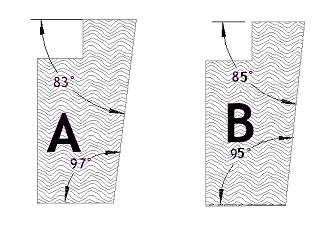 Below are the panel sizes in millimetres; you will need 30 Y panels, 45 X panels and 10 Z panels (remember that 5 Z panels are mirror images) 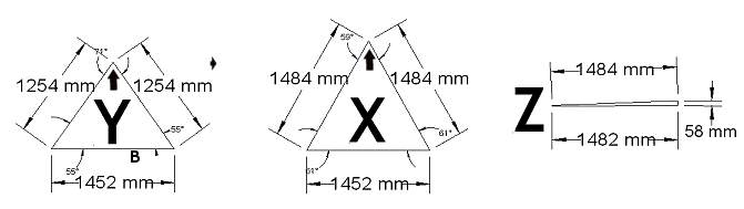 The B on the base of the Y panel shows were to use B struts (all other struts are A). Z panels don�t have any plywood infill they can be made from (A) struts cut into a wedge from 58mm to nothing. 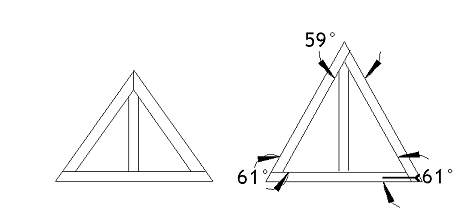 A brace section of stud can be fitted on the centreline of each panel; this strengthens the frame and makes it possible to use plywood infill sheets that are half the normal size (great for using up off-cuts). All of the panels can be cut efficiently from standard 8x4 sheet material. |
|
|
|
|
| [ comments 18 ] |
| posted by Colin | 16/03/2008 11:02:18 |
|
|
|
| Hi Paul It may be better to draw the end profiles of the struts (A+B) as parallograms with the long side horizontal on the page. Effectively the top and bottom of the timber are machined to form a parallelogram. As the drawings appear to show right angled corners on the left side, some readers may try to cut the timber that way ;) To visualise it, rotate the A+B strut end drawings 90 degrees clockwise. The "A" strut will have a 7 degree "lean" to the left at both ends, the "B" will have a 5 degree "lean" | |
|
|
|
| posted by Admin | 17/03/2008 02:13:20 |
|
|
|
Like this: Yes this way is better for larger sizes of timber because you only need to machine the ends which are a shorter cut. The rebate is a little more tricky because you have to add the 7 degree lean. Also the left edge is not at right angles to the covering material when the dome is finished. I've drawn a comparison between the two different types below:  One other thing Colin, when you make up the frames end cuts using my strut section will be at 90 degrees, Would you need a compound mitre for your section? |
|
|
|
|
| posted by Colin | 17/03/2008 11:19:56 |
|
|
|
| Hi Paul You shouldn`t need a compound angle as the timber will sit on the bed of the saw at an angle (cut vertically). From a strength point of view the triangles are best made up in the format of your last triangle picture (bottom right). The ends of the timber will need a compound angle :) With the other method you won`t have much material to fix into and the acute angles may be a problem depending on the saw used, miter saws can usually cut +/-45 degrees. I have a miserable cold atm so its hard to visualise stuff in the minds eye so i could be off on a tangent hehe. when i get a minute i`ll make up a couple of triangles using both methods. | |
|
|
|
| posted by Jeff | 20/03/2008 01:59:13 |
|
|
|
| Hey Guys, I understand the drywall etc attachment need for the interior strut edge to be cut at the 97 degree angle. But it occurs to be that the outer edge can be left at 90 degrees and then the 7 degree rabbit can be added by a common dovetail router bit (about 20 dollars at rockler.com/product.cfm?page=18707). To show this on the second A-strut drawing just draw a line straight down from the right edge of the rabbit connecting at 90 degrees to the bottom strut face. Advantages: less cutting, slightly longer strut extension into the dome interior, really easy rabbiting. Disadvantages: instead of where you show one 166 degree angle in the outside skin, there would be two 173 angles, one each at the edge of the rabbits, it would be like camfering the joints between the panels. | |
|
|
|
| posted by xxxromski | 11/12/2008 21:53:24 |
|
|
|
| Paul, In the 3V dome calculation toolyou show the Blue B strut angles as 78.5 + 78.5= 157 and here you show them as 166 or 168. Have I read it wrong? Rom | |
|
|
|
| posted by ANTHONY | 10/04/2009 00:05:19 |
|
|
|
| on the forth set of diagrams on this page they show the way each strut lays onto the next. does the strut length include or not include the width of its neighbour hope that makes sense didnt know how to explain my question thanks | |
|
|
|
| posted by Admin | 10/04/2009 20:21:57 |
|
|
|
| Hi Anthony, the strut length is from vertex to vertex, that's the very tip of the triangle so you would need to allow for the thickness of wood unless you do a mitre joint like the top of the left triangle. | |
|
|
|
| posted by Zick | 22/05/2009 18:30:56 |
|
|
|
| Just built two sample panels using both strut methods mentioned above. Referring to the drawing above showing both methods side by side, the right method takes quite a bit more work in setting up the cuts due to compound miters being required at each vertex, however it does provide a perfectly square interface when bolting panels together. The left method is less time consuming while building each panel, but extra care will be required when bolting panels together (the 7-degree lean comes into play for each bolt hole). For insulation concerns, the left method is better if you desire to use sheet insulation available at the nearest hardware store, but the right method is better for expanding foam type insulation. IMHO either method is excellent just so long as you understand where care needs to be taken in the process. One question I have concerning both methods is the Rebate. Is there a simple way to end the Rebate so it does not extend to the outside of the strut frame without using complex, or expensive methods? When cutting the rebate I tried to Dado the Rebate prior to assembling the frame but to get a square edge on the rebate, you must cut the entire length of the strut. This leaves a length of rebate at each vertex that is not covered by the panel. Any suggestions beyond hand chiseling the rebate in vertex of the frame? Thanks, | |
|
|
|
| posted by Paul | 22/05/2009 21:57:07 |
|
|
|
Hi Zick, I have used a spidle moulder to cut out below the base of the rebate, See attached diagram: Just set the spidle fence at the same angles as the mitre. This will work on the left method above, not sure how to do it with the right method though. Just set the spidle fence at the same angles as the mitre. This will work on the left method above, not sure how to do it with the right method though.
|
|
|
|
|
| posted by roger chen | 19/12/2010 03:19:35 |
|
|
|
| the sum of the interior angles of a triangle is 180 degrees. In the figure above you have 61+61+59 which gives 181 degrees. maybe 60.5 + 60.5 + 59? | |
|
|
|
| posted by Admin | 28/12/2010 22:32:59 |
|
|
|
|
Your quite right roger, Here's the exact angles, I round most of the angles and measurements on the site because machining to higher accuracy than say 0.5mm or 0.5 degrees is not really possible on the average DIY saw bench. |
|
|
|
|
| posted by Lukasz form Poland | 13/01/2011 16:49:27 |
|
|
|
| what will be the Z panel dimensions for 6m diameter dome. | |
|
|
|
| posted by leonardo | 22/08/2011 08:39:10 |
|
|
|
| Hi, In the third diagram the Y and X panels they both share the same base lenth.In the text you explain in your own words that, The B on the base of the Y panel shows were to use B struts (all other struts are A). So, Is the base of the X panel a A strut? the one with the same lenth of the Y panel with a different dihedral angle ?, Is that right? This is a wonderful page, great job ,thank you very much | |
|
|
|
| posted by Donamarie Goldsmtih | 30/06/2012 23:17:45 |
|
|
|
| What are the Z panels used for. I do not see any description of where or why to use them? | |
|
|
|
| posted by Donamarie Goldsmith | 03/07/2012 21:04:49 |
|
|
|
| Love this site. A lot of really good information. My question has to do with accessories for using the dome for a greenhouse. How are you venting the dome. All of your joints appear to be fixed. I need to vent in the summer and be able to heat in the winter at my location. I can get 3 feet or more snow and it can get to 100 degrees in the summer. | |
|
|
|
comments will be accessed through the forum in the new site design (coming soon)
14873
Copyright © 2007- 2014 geo-dome.co.uk. All Rights Reserved.